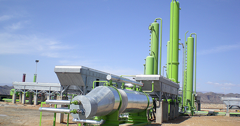

Amine Sweetening
| SPEC can take your gas analysis to design the Amine system suitable for your specific process requirements. The equipment can be totally mounted on skid and pre-packaged in our fabrication facilities to reduce on-site installation time and cost. |
Sweetening of Natural Gas
| Natural Gas often contain carbon dioxide (CO2), hydrogen sulfide (H2S) and other sulfur compounds which may require removal if their concetrations are above the acceptable limit. Carbon dioxide and hydrogen sulfide are known as acid gases because in the presence of water they form carbonic acid and sulfuric acid, respectively. When H2S and other sulfur
compounds concentrations in the natural gas exceed acceptable limits, the natural gas is considered to be a “sour gas” and requires removal. The process of removing the H2S and other sulfur compounds is known as gas sweetening.
The key factors for gas sweetening are:
|
|
 |
 |
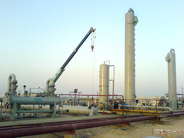
Process Description
The sour gas passes through an inlet scrubber to remove contaminants before coming in contact with AMINE which helps
ensure proper performance of the AMINE. The scrubbed sour gas enters the absorber tower where it comes in contact with the
down-flowing AMINE. Trays or structured packing inside the absorber provide adequate contact are for the AMINE to absorb
the sour gases. As a result, the concentration of sour gases in the upward flowing, natural gas decreases, or becomes sweater,
while the lean, downward flowing AMINE absorbs the sour gases. The sweet gas exits the absorber at the top while the AMINE
containing the sour gas, or rich AMINE, exits at the bottom of the absorber.
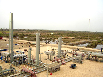
The rich AMINE exits the buttom of the absorber and passes through a flash tank to remove any hydrocarbons or hydrocarbon condensates from the rich AMINE. From the flash tank, the rich AMINE passes through a rich/lean AMINE exchanger preheating the rich AMINE before it enters the AMINE stripping tower. The heat from the reboiler allows for the acid gasses to dissociate from the AMINE. The acid gasses exit the top of the still column while the lean AMINE exits from the buttom. The removed acid gases are condensed and cooled in the reflux condenser. The condensed steam is separated in the reflux accumulator and send back to the still column while the acid gases are vented or sent back to the still column while systems. The lean AMINE passes through the rich/lean AMINE exchanger cooling it down. The cooled AMINE is pumped to absoreber pressure prior to entering the absorber where the entire repeats itsel.
Software Utilization
SPEC utilizez PROMAX with TSWEET by Bryan Research & Engineering, a specialized simulation software providing optimized
solutions for AMINE plants. By using the latest software SPEC is able to accurately and throughly design AMINE plants ensuring
all variables have been taken into account. By incorporatingthe latest software coupled withprograms developed in-house and
years of experience designing AMINE plants, SPEC can guarantee its AMINE plants meet design specifications.
Advantage of Amine Sweetening
- Removal of high concetration of acid gases
- Continuous process allowing for AMINE regeneration
- Organic sulfur compounds can be removed with the addition of physical solvents
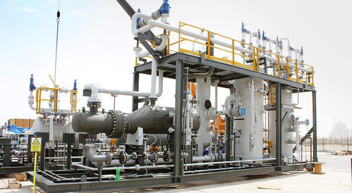 |
Standard Equipment List
1. Absorber
2. Inlet Scrubber (typically integrated with absorber)
3. Flash Tank
4. Filters
5. Amine Reboiler
6. Reflux Accumulator
7. Surge Tank
8. Still Column
9. Booster Pump
10. Circular Pump
11. Reflux Pump
12. Heat Exchangers
13. Analog Pressure / Temperature indicators
14. Pneumatic Controllers
15. Pneumatic Control Valves
16. Pressure Safety Valves
Optional Equipment List
1. Process
2. Spare Pumps
3. Integrated Electro/Pneumatic system with PLC System
4. Hot Oil System