Equipment
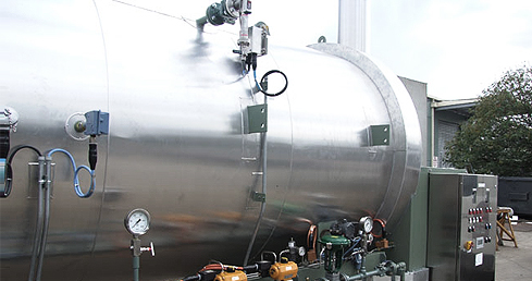
Water-bath heaters provide indirect heating for gas, crude and other process fluids within the operating temperature range of the selected design.

Application
Process
Fuel gas or fuel oil is burned within the horizontal “U”-shaped firebox immersed in the lower portion of the water bath. Heat released by the burning fuel transmits quickly through the firetube wall to the bath, holding it at the desired temperature.
The fluid to be heated (wellstream, natural gas, oil or water) flows through the process coil immersed in the upper portion of the bath. Heat passes from the hot water through the tube wall to the fluid inside the coil.
The heater temperature controller maintains bath temperature by controlling the firebox fuel gas supply. 87 °C is the maximum bath operating temperature, and it is preferable to run below that wherever inlet conditions and outlet temperature requirements allow.
Operating temperature is selected to provide the required downstream process conditions while managing fuel use.
System configuration
System configuration varies with process duty, operating conditions and project requirements.

Carbon steel vessel on two saddle supports that holds the water bath around the firetube and the process coil.
Single or multiple U-shaped firetubes in the lower part of the shell, where the burning fuel heats the bath.
Seamless-pipe coil above the firetube that carries the fluid being heated; the only part above atmospheric pressure.
High-efficiency burner with fuel gas manifold and fuel gas preheat coil; the temperature controller holds the bath at set point.
Top-mounted vessel with thief hatch, fill connection, level gauge and temperature gauge.
Carries the combustion gases away, with rain cap and bird screen.
Also in the scope of supply
Final equipment arrangement and delivery format depend on process duty, transport constraints and site requirements.
Specifications
| Electro-pneumatic instrumentation | Function |
|---|---|
| Low level switch | Protects against loss of water bath level |
| High temperature switch, flue stack mounted | Shuts down on over-temperature |
| Temperature controller (transmitter or pneumatic) | Holds the bath at set point by modulating fuel gas |
| Low pressure switch, fuel gas | Protects the burner on loss of fuel gas pressure |
| Parameter | Value |
|---|---|
| Maximum bath temperature | 87 °C |
| Process coil code | ASME Section VIII, Division 1, seamless pipe |
| Coil inspection | 100% radiographed |
| Fuel | Fuel gas or fuel oil |
SPEC designs each heater to the client's specification and duty.
Evidence
For Tullow Pakistan at the Chacher gas field and Dewan Petroleum at the Salsabil gas field, both in Pakistan, SPEC designed, fabricated and commissioned a water bath oil heater as part of each gas processing facility.
Related
Hot oil circulation where individual fired heaters are not selected.
View →Pig trap systems for pipeline maintenance.
View →Separation that upstream heating can improve.
View →Process data

Enquiries
Send us your process data and operating conditions, and we will review the duty with you.
Contact Us