Equipment
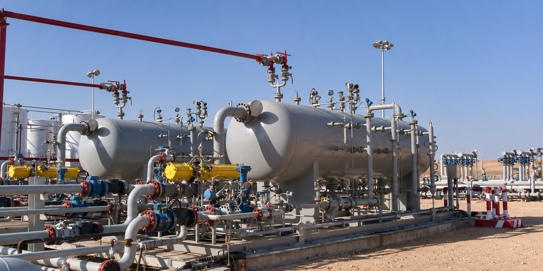
Vertical and horizontal separators that split well fluids into gas and liquid, or into gas, oil and water, using momentum, gravity settling and coalescing. Orientation and configuration are chosen for the specific application.
Application
Separators use one or more of the following to achieve separation:
Separators are supplied in two major orientations, vertical and horizontal, and as either two or three phase units. Each orientation carries its own operational advantages and the selection follows the specific application.
Sizing
Beyond the capacity of the incoming liquids and gases, these fluid characteristics set the appropriate separator design:
| Characteristic | Why it matters |
|---|---|
| Gas to liquid ratio | Sets the balance between vapour handling and liquid retention volume |
| Density differences | Between gas and liquids, and between the liquids themselves |
| Differences in viscosity | Affects settling behaviour and separation time |
| Operating temperature and pressure | Governs vessel rating and phase behaviour |
| Particulate size | Determines the internals required to capture the finer fraction |
| Presence of H₂S or CO₂ | Drives material selection; H₂S service additionally requires NACE compliance |
| Slug volumes | Sets the surge capacity the vessel must absorb |
Process
Separation begins as the process fluid enters the separator and contacts the inlet device, which reduces the momentum of the inlet stream. This is the first stage of separation. The main inlet devices used are diverter plates, half pipe, vane and cyclonic, selected against the process conditions.
After that initial bulk separation, the fluid velocity is further reduced by the increased cross-sectional area, allowing liquid particles to drop into the liquid accumulation section. Any liquid still carried in the gas after those two stages is removed by mist extractors installed before the gas outlet nozzle; several types of mist extractor are used.
Liquid collects in the accumulation section. Liquid-retention time is set from fluid properties, separation duty and required outlet quality. In a two-phase separator the accumulation section is common to both liquids; a three-phase separator adds a further accumulation section for the separated oil.
System configuration
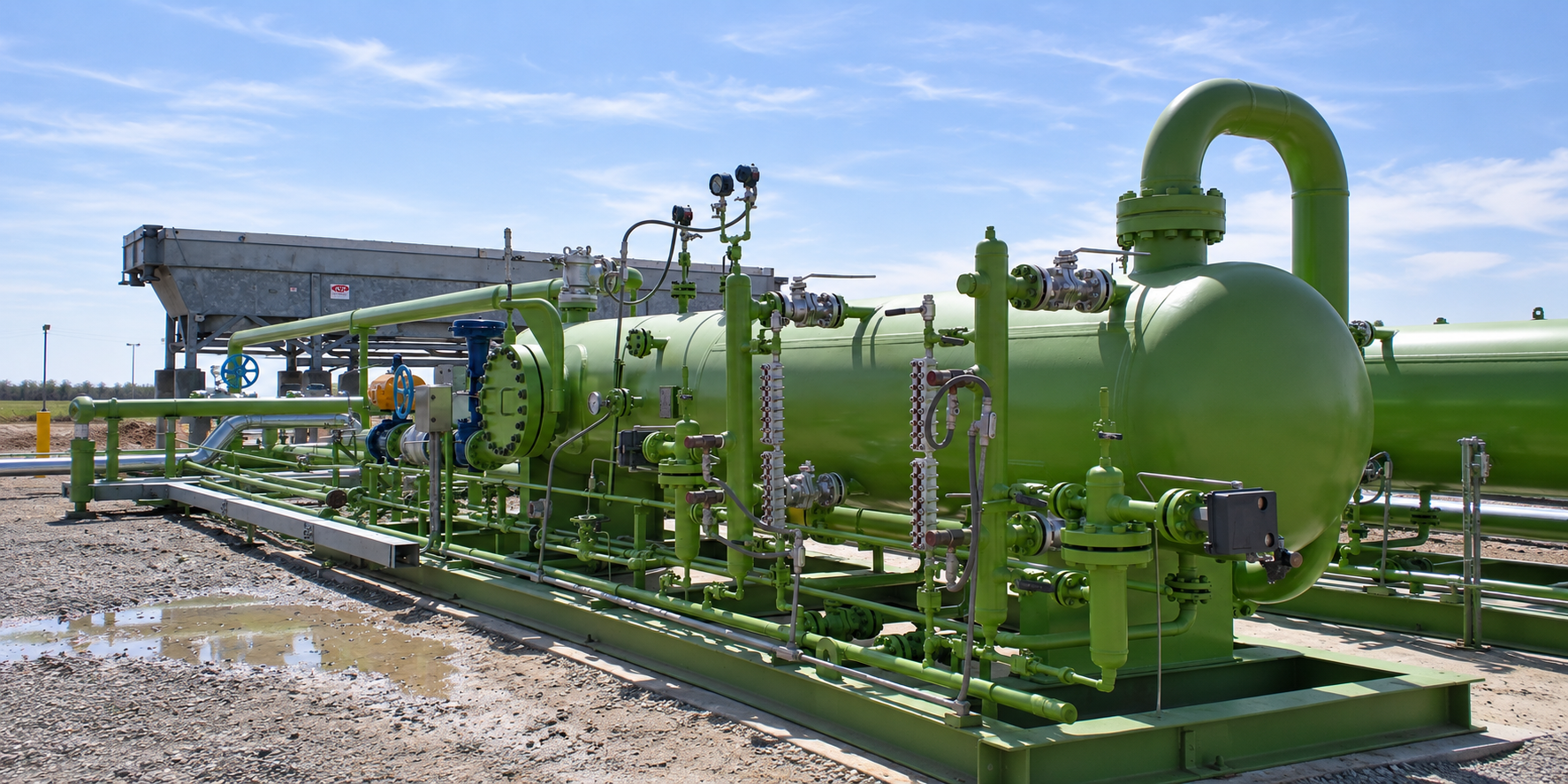
System configuration varies with process duty, operating conditions and project requirements.
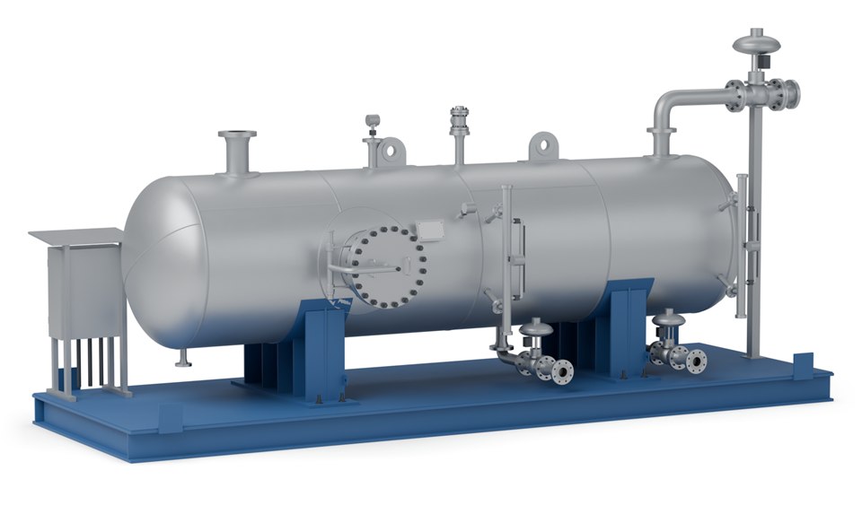
Diverter plate, half pipe, vane or cyclonic inlet that breaks the momentum of the incoming stream: the first stage of separation.
Holds the liquid for the retention time the duty needs; a three-phase separator adds a section for the separated oil.
Removes the liquid still carried in the gas, ahead of the gas outlet nozzle.
Control the gas and liquid outlets, with interface control on three-phase duty.
Pressure, temperature and level gauges with the safety devices.
Separator and instrumentation on a common skid for installation and operation.
Design basis
Options
Vessel dimensions, design pressure and capacity are set against your process conditions, including separators built to the client's own specification. Final equipment arrangement and delivery format depend on process duty, transport constraints and site requirements.
Evidence
For the 100,000 BOPD West Qurna-1 wet crude treatment system in Iraq, SPEC designed and fabricated modular coalescer and balance vessel skids, supplied to CPECC. Each assembled module weighed over 100 tonnes and stood higher than two storeys. SPEC also supplied separator equipment for the Meseda field expansion at Ras Gharib, Egypt.
Related
Coalescing separators removing solids and fine aerosols from gas.
View →Separating liquids of different densities where no emulsion exists.
View →For the emulsions a separator alone cannot break.
View →Process data

Enquiries
Send us your process data and operating conditions, and we will review the duty with you.
Contact Us