Equipment
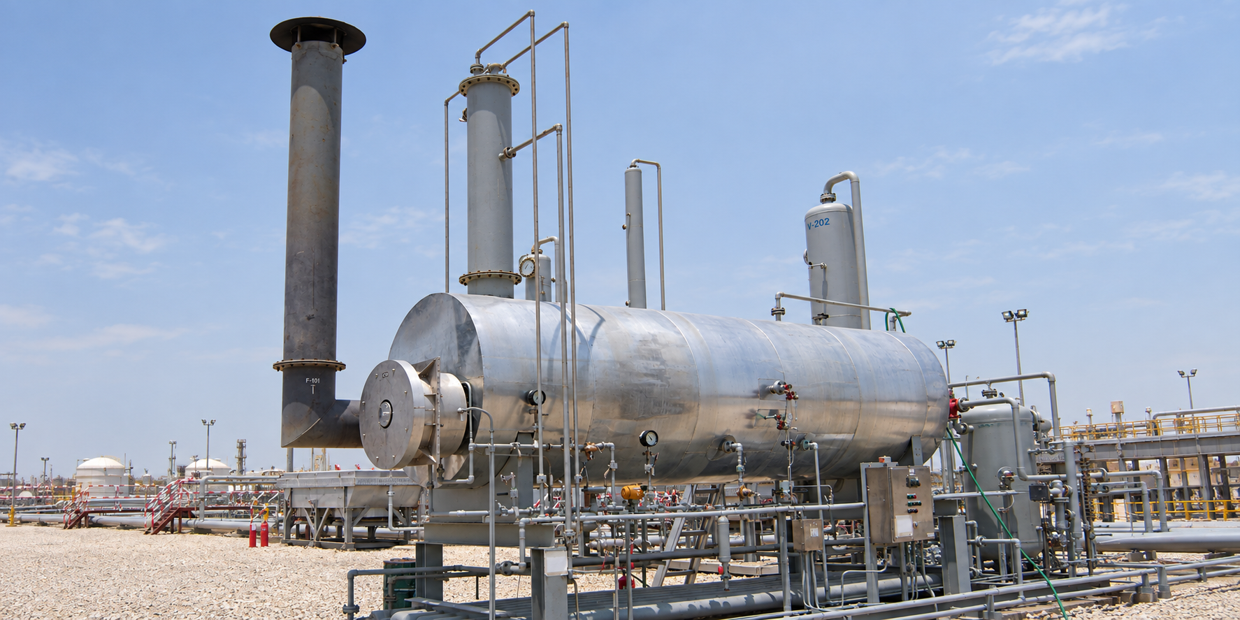
Mechanical heater treaters use heat, residence time and coalescing internals to promote emulsion breaking and water removal.
Application
Where produced water is bound into an emulsion, gravity separation alone will not release it. The heater treater applies heat to reduce viscosity and weaken the emulsion, then gives the fluids the residence time and coalescing surface they need to separate.
Designs cover duties above 20,000 barrels of liquid per day (BLPD) and low-API crude.
Process
The heater treater consists of two main sections: the heating section and the coalescing section.
The heating section contains firetubes which heat the produced fluids to the appropriate treating temperature. Produced fluids enter above the firetubes and are directed downwards until they are distributed across the heating section. Associated gas leaves the vessel through a back pressure control valve, and free water is removed from the bottom.
The heated process fluid then passes through the surge section and into the coalescing section. Oil passes through the coalescers and is drawn off at the top as treated oil; treated water is removed from the bottom of the treater.
System configuration
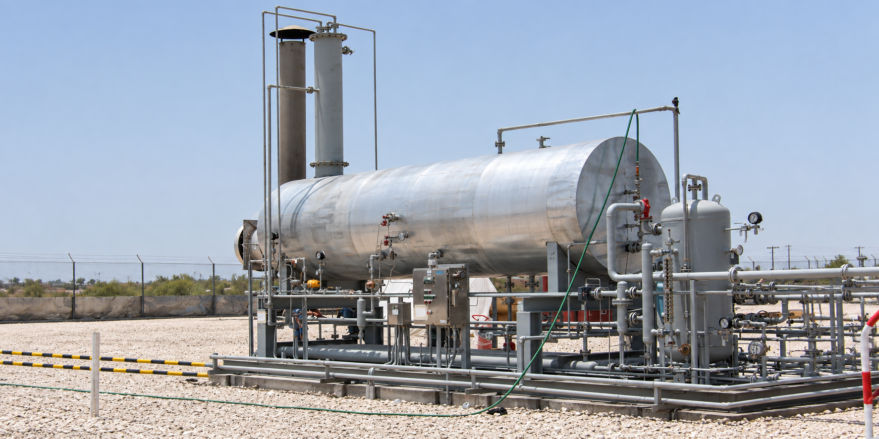
System configuration varies with process duty, operating conditions and project requirements.

Spreads the incoming emulsion in a thin film so that the gas breaks out quickly.
Firetubes heat the produced fluids to treating temperature; free water is drawn off from the bottom.
Transfers the heated fluid from the heating section to the coalescing section.
Coalescers merge the remaining water droplets: treated oil leaves at the top and treated water at the bottom.
Releases the associated gas from the vessel.
Fully automated system that operates the firetubes safely and efficiently.
Final equipment arrangement and delivery format depend on process duty, transport constraints and site requirements.
Specifications
| Parameter | Value |
|---|---|
| Orientation | Horizontal, skid-mounted |
| Treating capacity | Sized to duty, including above 20,000 BLPD |
| Crude range | Including low-API crude |
| Heat source | Firetubes within the heating section |
| Control | Fully automated burner management system |
Treating temperature, vessel size and firetube duty are set by SPEC engineering against your crude properties and water cut.
Advantages
Skid-mounted construction can reduce site installation work.
The burner management system (BMS) operates the treater safely and efficiently.
Configured around process requirements, operating conditions and project scope.
Related
Lower BS&W and salt targets, or reduced plot area, where the design basis supports it.
View →Reducing vapour pressure to export specification.
View →Removing free water upstream to cut the treating duty.
View →Process data

Enquiries
Send us your process data and operating conditions, and we will review the duty with you.
Contact Us