Equipment
Stabilizers remove light ends from crude or condensate to meet the specified vapour-pressure limit for storage, transport or export.
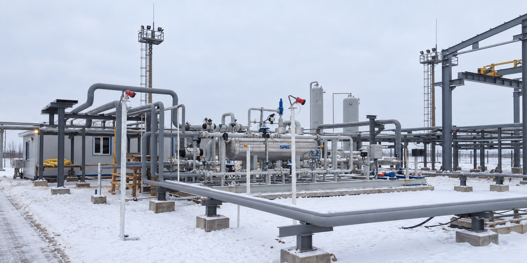
Gas Treatment Units for Two Fields Makat and Balgymbaeva Fields, Kazakhstan 2013
View project →ScopeCondensate stabilization unit alongside glycol dehydration and dew point control for associated gas.
Application
Crude and condensate stabilizers are used in process plants to meet the Reid vapour pressure requirements specified by the customer. Stripping the light ends brings the true vapour pressure inside the limit set for storage and export.
A similar arrangement is also offered for H₂S stripping from liquid, where the sales product has to meet a maximum allowable H₂S content.
Process
The typical stabilizer arrangement is a stabilization column with process trays or packing installed, together with a stabilizer reboiler.
On smaller units the stabilizer column is sometimes mounted directly on the reboiler. Larger units have separate columns and reboilers. Some systems also include inlet stabilized/unstabilized heat exchangers and an overhead reflux condenser, for enhanced recovery and a more efficient design.
System configuration
System configuration varies with process duty, operating conditions and project requirements.
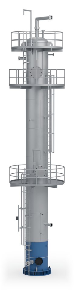
Strips the light ends from the crude or condensate over process trays or structured packing.
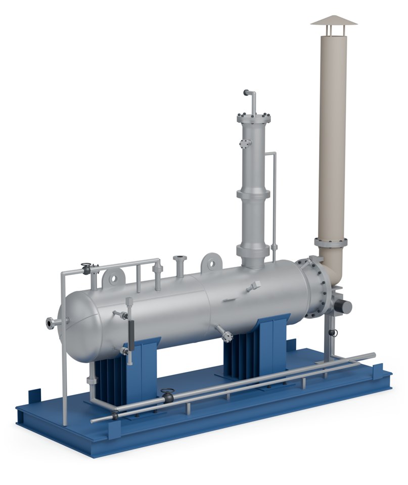
Supplies the heat that drives the light ends out of the liquid; gas fired, or heated by hot oil or steam.
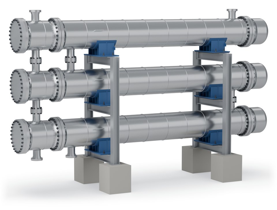
Optional: heat exchange between the stabilized product and the incoming feed, for a more efficient design.
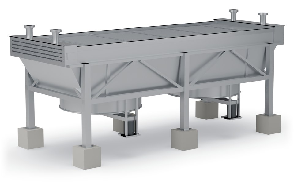
Optional: condenses overhead vapour as reflux, for enhanced recovery.
Arrangement
Options
Units can be supplied as skid-mounted modules. Final equipment arrangement and delivery format depend on process duty, transport constraints and site requirements. Column diameter, tray count, reboiler duty and the target RVP are set against your feed and product specification.
Advantages
Configured around feed properties, utility availability and required product specification.
Sour service materials and detailing where H₂S is present in the stream.
Gas fired, hot oil or steam depending on what the site can supply.
Related
Heat and residence time to break the emulsion and drop water out.
View →An electrostatic grid for lower BS&W and lower salt content.
View →The separation stage upstream of stabilization.
View →Process data

Enquiries
Send us your process data and operating conditions, and we will review the duty with you.
Contact Us