Equipment
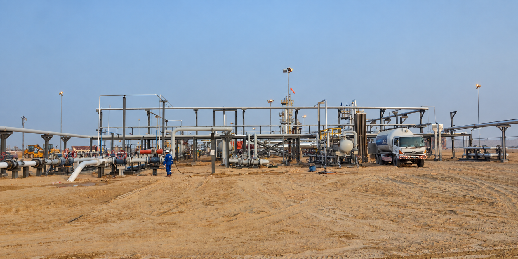
Where higher recovery of ethane and propane is required than dew point control can reach, a cryogenic plant is needed. In the gas industry, cryogenic temperature typically means below −45 °C.
Application
Two methods are used to reach cryogenic temperatures: turbo expanders and J-T valve expansion. The choice follows the gas flow rate, the available pressure and the ethane recovery target.
Route 1
Typically used for smaller gas flows. It is cheaper to install and operate than a turbo expander unit, but yields lower ethane recovery. The process uses the Joule-Thomson effect, and requires a high differential pressure across the J-T valve together with sufficient heat exchange.
The gas is first dried, typically using molecular sieve units, to reach water concentrations below 1 ppm. The dry gas is cooled in a heat exchanger before being expanded across the J-T valve. After the valve, liquid is sent to the de-methaniser tower while the overhead gas cools the inlet feed gas in the heat exchanger. Mechanical refrigeration can be added to increase efficiency or to compensate for lower gas pressure.
| Advantages | Limitations |
|---|---|
| Lower installed and operating cost than a turbo expander | High pressure required |
| Simple design and operation | Cannot achieve ethane recoveries as high as turbo expanders |
| No rotating equipment required | — |
Route 2
Turbo expanders are the predominant process for recovering ethane from gas. A turbine expands the gas to cool it to around −101 °C, substantially lower than a J-T valve alone can reach.
Molecular sieves dry the gas below 1 ppm ahead of the turbo expansion process. Depending on gas composition, a gas/gas exchanger provides initial cooling of the incoming dry gas; on a richer composition, mechanical refrigeration may be required. The cooled gas is sent to a cold separator. From there a J-T valve and turbo expander work in parallel: the J-T valve handles the bottoms and the top gas goes to the turbo expander. Both liquid streams are then sent to a de-methaniser tower, which removes methane at the top and NGL at the bottom.
System configuration
System configuration varies with process duty, operating conditions and project requirements.
Route 1
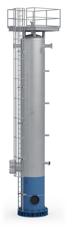
Dry the feed gas to a water content below 1 ppm before it is chilled.
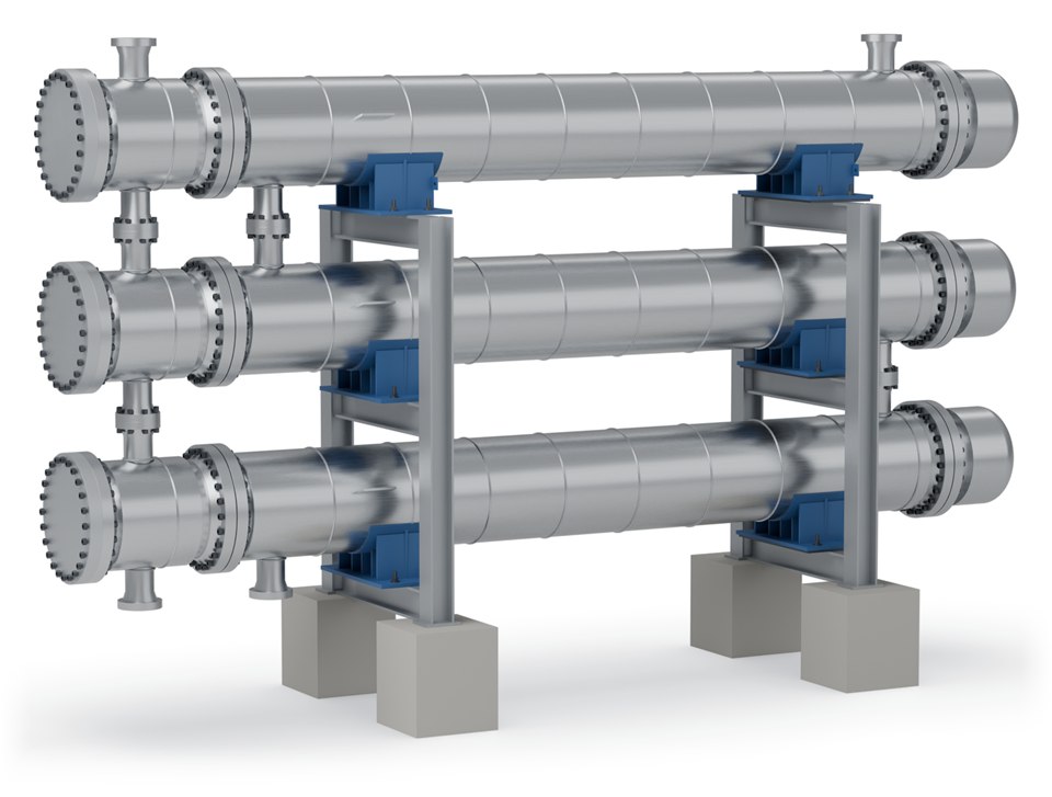
Cools the dry gas against the cold overhead gas, ahead of the J-T valve.
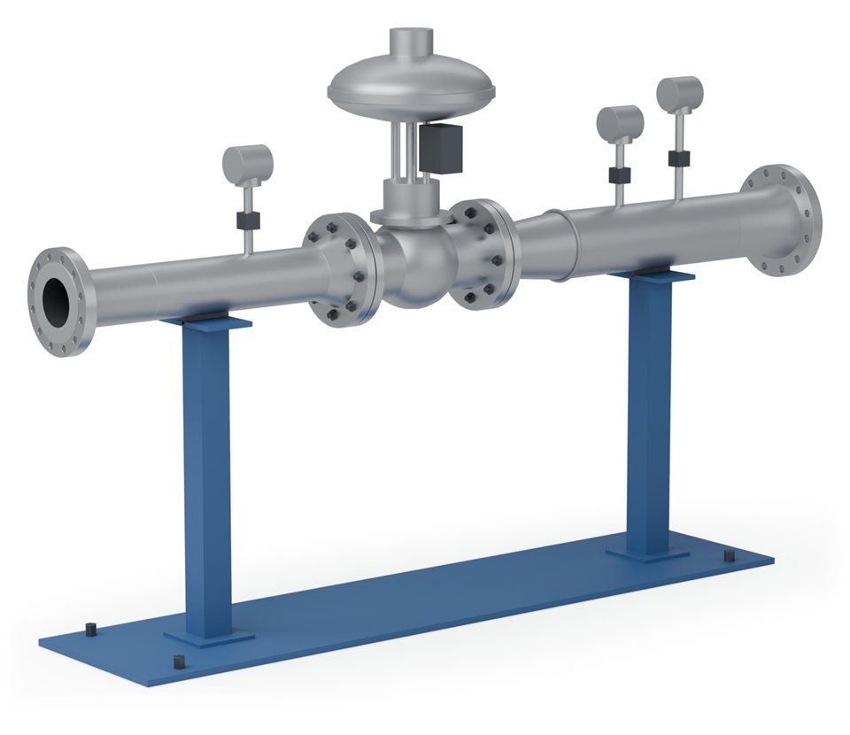
Expands the gas across a high pressure differential, which cools it by the Joule-Thomson effect.
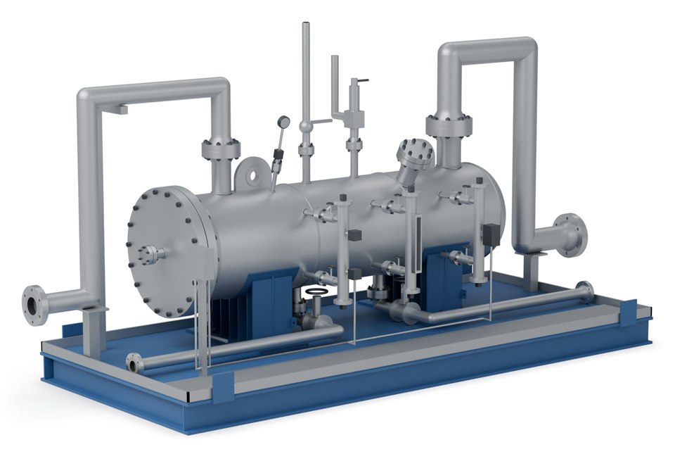
Separates the liquid formed on expansion from the cold gas.

Removes methane at the top and leaves the natural gas liquids at the bottom.
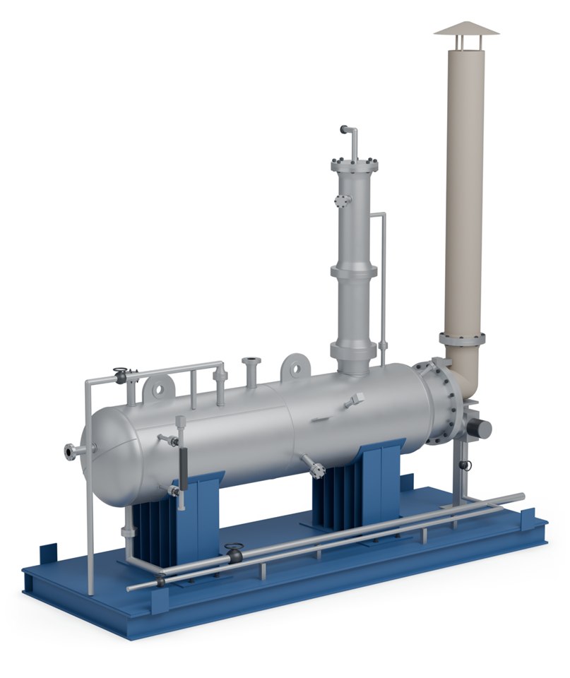
Introduce heat at the bottom of the de-methaniser.
Route 2
Dry the feed gas to a water content below 1 ppm ahead of the turbo expansion process.
Gives the incoming dry gas its initial cooling; a richer gas may also need mechanical refrigeration.
Splits the cooled stream: the top gas goes to the turbo expander and the bottoms to the J-T valve.
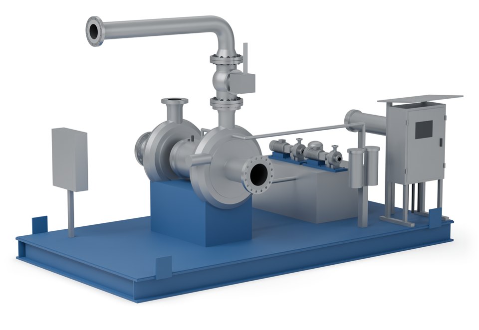
Expands the gas through a turbine, cooling it to around −101 °C.
Handles the separator bottoms, working in parallel with the turbo expander.
Receives both liquid streams, removing methane at the top and NGL at the bottom.
Final equipment arrangement and delivery format depend on process duty, transport constraints and site requirements.
Specifications
| Parameter | Value |
|---|---|
| Cryogenic temperature (industry definition) | Below −45 °C |
| Turbo expander outlet temperature | Typically around −101 °C, depending on operating conditions |
| Feed gas water content | Below 1 ppm, achieved by molecular sieve |
| J-T route suits | Smaller gas flows, high available differential pressure |
| Turbo expander route suits | High ethane recovery targets |
Recovery percentages, tower sizing and refrigeration duty are set by SPEC engineering against your feed composition and product targets.
Related
The lighter-duty route where deep recovery is not required.
View →Drying the feed gas below 1 ppm ahead of the cold section.
View →Fractionating the NGL the de-methaniser produces.
View →Process data

Enquiries
Send us your process data and operating conditions, and we will review the duty with you.
Contact Us