Equipment
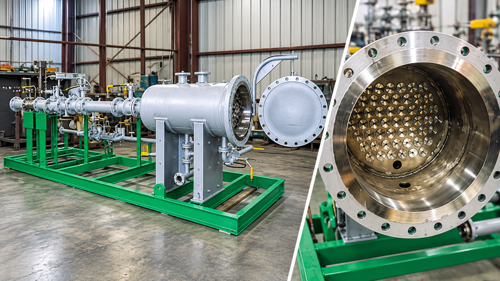
Hydrocyclones remove free oil from produced water by centrifugal force, with no moving parts. Where process pressure allows, they are installed upstream of flotation equipment such as an IGF as the first treatment stage.
Application
Oil and gas production yields significant quantities of water. Produced-water volumes and quality vary over the life of a field. That water must be separated and disposed of properly — by reinjection into the well for disposal or reservoir pressure maintenance, or by onshore or offshore discharge.
Hydrocyclones are the preliminary separation step where the process carries enough pressure to drive them, taking the bulk of the free oil out before the water reaches the flotation stage.
Process
The hydrocyclone is a vessel containing “liners” — centrifugal devices with no moving parts, used to separate liquids of different densities, most often free oil from water.
Fluid to be treated is directed tangentially into the hydrocyclone, which causes it to swirl. The spinning motion creates strong centrifugal forces that drive the two immiscible liquids apart. Because of the density difference, the heavier liquid is forced outward towards the wall of the liner while the lighter liquid is displaced towards the centre, where it forms a core.
By controlling the pressure across the tube, the lighter liquid is forced out through the overflow and the heavier liquid is directed to the underflow.
System configuration
System configuration varies with process duty, operating conditions and project requirements.
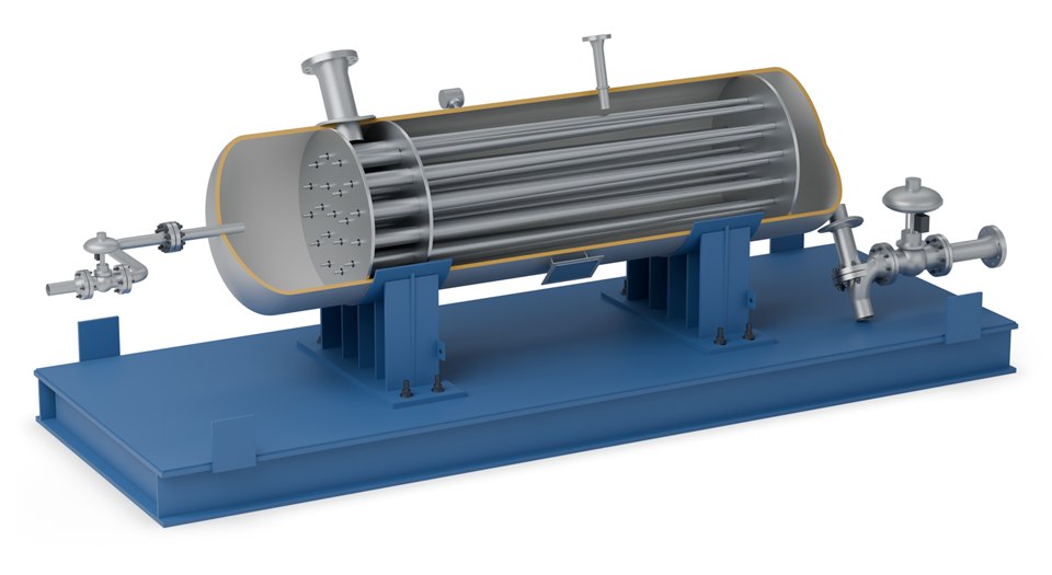
ASME-coded pressure vessel that houses the liners.
Centrifugal tubes with no moving parts: the tangential inlet makes the water swirl, driving the oil to the centre and the water to the wall.
Pressure control across the liners sends the oil out through the overflow and the water to the underflow.
Supplied as complete skid-mounted packages. Final equipment arrangement and delivery format depend on process duty, transport constraints and site requirements.
Specifications
| Parameter | Value |
|---|---|
| Typical outlet quality | As low as 25 ppm oil in water, depending on inlet water quality and droplet size |
| Vessel code | ASME Section VIII |
| Vessel sizes | Configured around process requirements, operating conditions and project scope |
| Materials | A range of materials and sizes depending on application |
| Moving parts | None |
| Delivery | Skid-mounted units |
| Typical position | Upstream of IGF, where process pressure allows |
Liner count, vessel size and the achievable outlet concentration are set by SPEC engineering against your inlet water quality and flow rate. Performance for a specific project is confirmed in SPEC’s proposal.
Advantages
Separation is driven by the pressure drop across the liner, not by rotating equipment.
Little to service, which matters on remote and offshore installations.
Typically 25 ppm oil in water or lower, subject to inlet conditions.
Related
The alternative where process pressure will not drive a hydrocyclone.
View →The flotation stage a hydrocyclone typically feeds.
View →Final polishing where discharge limits are tight.
View →Process data

Enquiries
Send us your process data and operating conditions, and we will review the duty with you.
Contact Us