Equipment
A produced water clarifier using dispersed gas and coalescing internals. Fuel gas is induced into the oily water as fine bubbles which attach to suspended oil droplets and float them to the surface, where the froth is skimmed off.
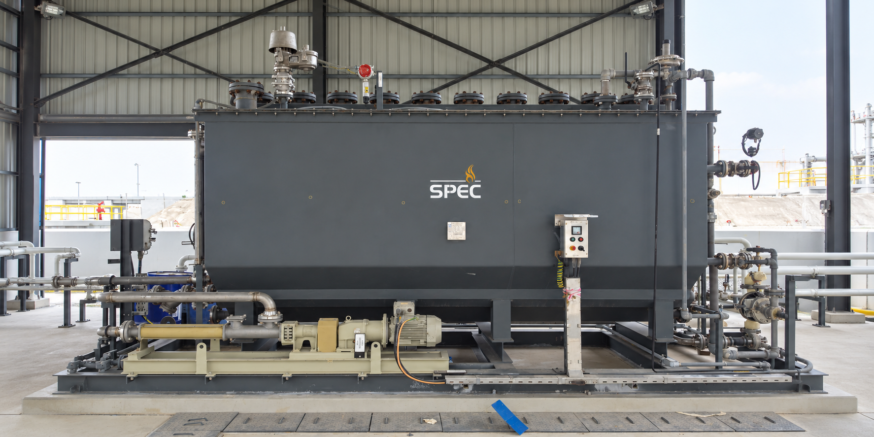
Produced Water System for the Abu Dhabi Crude Pipeline United Arab Emirates 2013
View project →ScopeOily and produced water treatment system with induced air flotation units, chemical dosing skids and pumps.
Application
Induced gas flotation (IGF) is one of several technologies available for treating produced water. IGF is used to remove dispersed oil and suspended solids from produced water.
Process
The unit disperses natural gas as fine bubbles through the total produced water stream by means of a differential pressure induction system. Recirculation pumps pressurise the water manifold that supplies the venturi eductors.
As pressurised water flows through the venturi eductors, blanket gas is induced into and mixed with the water. The water and gas mixture is ejected from the eductor bottoms, and the resulting small bubbles rise through the effluent stripping entrained oil.
As the gas-rich effluent proceeds it passes through the coalescing screens, which enhance oil removal. The stripped oil rises to the surface as froth, and the internal vessel hydraulics propel that froth over the oil bucket-skimming weir.
System configuration
System configuration varies with process duty, operating conditions and project requirements.
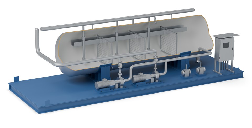
Static jet pumps, driven by water, that induce gas bubbles into the oily water; each can be reached through the water manifold and removed.
Two electric motor driven pumps that circulate water from the outlet back through the eductors.
Enhance oil removal as the gas-rich water passes through.
Receive the froth that the vessel hydraulics push over the weir.
Two double diaphragm pumps that send the recovered oil to the wet oil tank or the heater treater.
Pumps and eductors sit outside the vessel for easy access. Final equipment arrangement and delivery format depend on process duty, transport constraints and site requirements.
Specifications
| Parameter | Value |
|---|---|
| Typical outlet quality | As low as 10 ppm oil in water, depending on inlet conditions |
| Orientation | Vertical and horizontal options |
| Vessel code | ASME Section VIII |
| Supply | Configured around process requirements, operating conditions and project scope; skid-mounted |
| Moving parts | Minimal or none within the vessel |
| Options | Coagulant chemical injection; impeller or sparger design |
Vessel size, compartment count and eductor selection are set by SPEC engineering against your inlet water quality and flow rate. Performance for a specific project is confirmed in SPEC’s proposal.
Related
The same unit fitted with coalescer packs and diverter plates.
View →Preliminary separation typically installed upstream of the IGF.
View →The polishing stage where discharge limits are tighter.
View →Process data

Enquiries
Send us your process data and operating conditions, and we will review the duty with you.
Contact Us