Equipment
Hydrocarbon dew-point-control systems lower the hydrocarbon dew point by cooling and separating condensed liquids from the gas stream.
.png)
Sour Gas Processing Plant for Dewan Petroleum Salsabil Gas Field, Pakistan 2008
View project →ScopeHydrocarbon dew point control in the process train of a 60 MMSCFD sour gas plant.
Application
The hydrocarbon dew point of a gas moves with its pressure and composition. The process route is selected around gas composition, available pressure differential and required hydrocarbon-dew-point specification.
Route 1
Given sufficient pressure, low temperature separation units can be used for dew point control. LTS units work on the Joule-Thomson effect: gases cool when expanded at constant enthalpy from a higher pressure to a lower one, and that cooling causes hydrocarbons to condense.
High pressure gas enters a heat exchanger coil at the bottom of the separator, where it is cooled. A high pressure separator removes any water or condensate formed by that cooling. The gas then passes through a reducing valve where Joule-Thomson expansion occurs. Hydrocarbon liquid drops to the bottom of the separator, and the gas leaves with a hydrocarbon dew point set by the temperature and pressure of the separator. Glycol injection can prevent hydrates where no dehydration unit is installed upstream.
Route 2
Where sufficient pressure is not available for LTS, mechanical refrigeration is used for dew point control and hydrocarbon removal.
Inlet gas passes through a gas/gas heat exchanger, where gas leaving the cold separator cools the warm incoming gas. The inlet gas then heads to a chiller — typically a kettle type shell and tube exchanger using propane as the refrigerant. From the chiller, gas and liquid are separated in a three phase separator into water and glycol, liquid hydrocarbon, and gas. The liquid hydrocarbon is sent to distillation towers for separation into its individual components. The top gas is used in the gas/gas heat exchanger and then leaves the plant.
| Major equipment |
|---|
| Gas/gas heat exchanger |
| Chiller — typically kettle type shell and tube, propane refrigerant |
| Cold separator |
System configuration
System configuration varies with process duty, operating conditions and project requirements.
Route 1
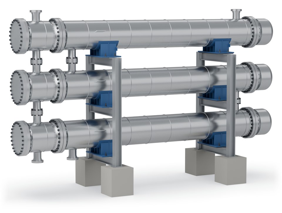
Cools the high-pressure inlet gas against the cold gas leaving the separator, ahead of the expansion valve.
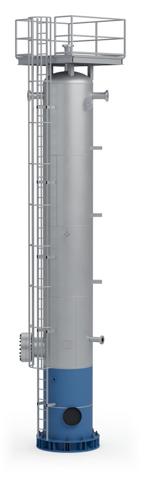
Removes the water and condensate that form as the inlet gas is cooled, before expansion.
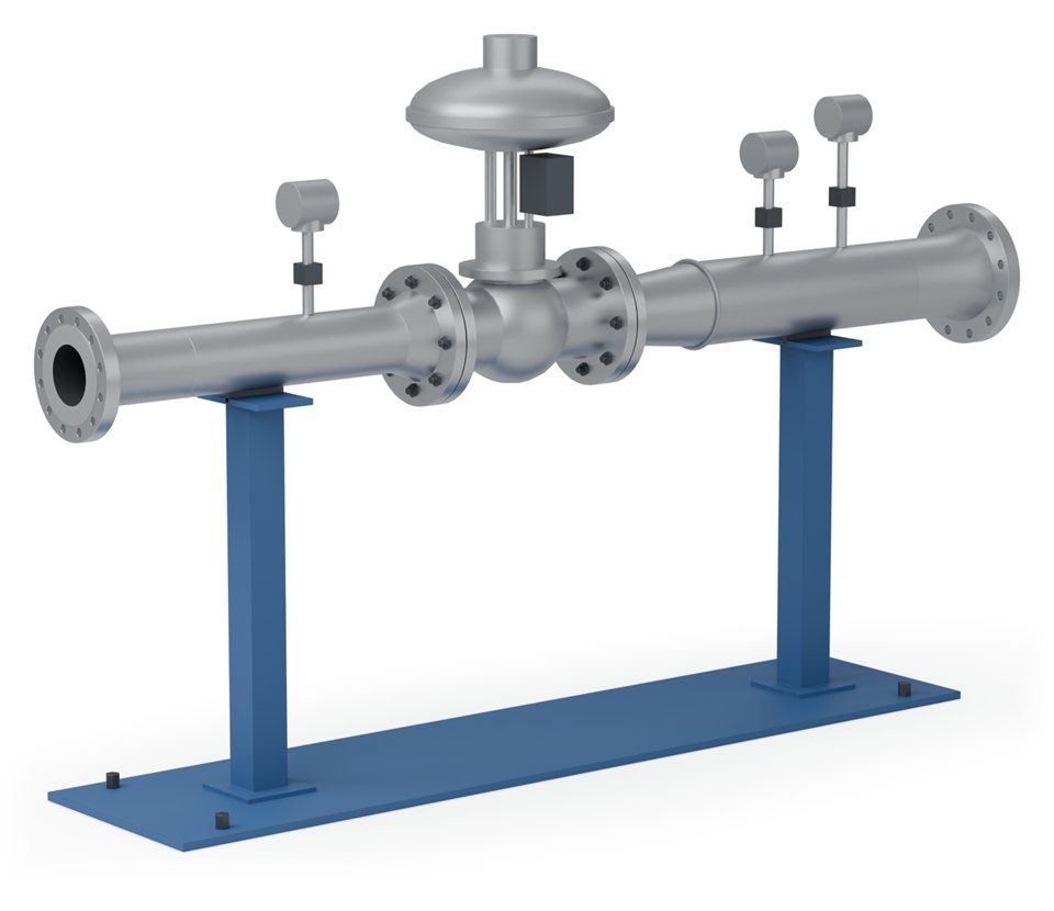
Reduces the gas pressure, so the gas cools by the Joule-Thomson effect and hydrocarbons condense.
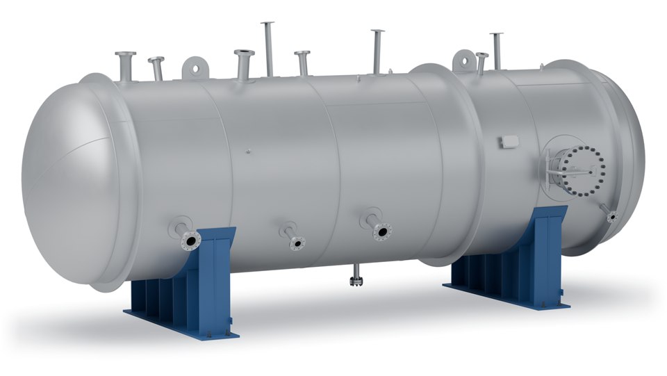
Separates the condensed hydrocarbon liquid from the cold gas, with an integrated heating coil in its base.
Units can be supplied skid-mounted. Final equipment arrangement and delivery format depend on process duty, transport constraints and site requirements.
Selection
| Condition | Route |
|---|---|
| High pressure gas available | Low temperature separation (Joule-Thomson) |
| Insufficient pressure for LTS | Mechanical refrigeration |
| No upstream dehydration | Glycol injection for hydrate prevention |
| Deeper ethane and propane recovery required | A cryogenic plant rather than HCDPC |
SPEC's engineers will advise which HCDPC process suits your application. Send us your gas analysis and target dew point.
Related
Where higher ethane and propane recovery is required.
View →Fractionation of the recovered liquid into products.
View →Upstream dehydration that removes the need for glycol injection.
View →Process data

Enquiries
Send us your process data and operating conditions, and we will review the duty with you.
Contact Us